Software approach
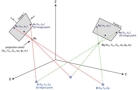
The last decade has witnessed new insights in the geometry of multiple images and powerful image orientation techniques from the field of computer vision have started to emerge as viable alternatives. Using techniques such as triangulation, an image point occurring in at least two views can be reconstructed in 3D (see figure below).
Mapping of 3D object points onto 2D points in two aerial frame images.
However, this requires the knowledge of the interior and exterior orientations of the images. In computer vision, these orientation parameters can be determined by an approach called Structure from Motion. Besides, SfM also computes a set of sparse 3D points along that represent the scene structure. SfM only requires corresponding image features occurring in a series of overlapping photographs captured by a camera moving around the scene.
It is essential to understand that the SfM output is equivalent to the real-world scene up to a global scaling, rotation and translation. These parameters can only be recovered via the use of additional data such as ground control points (GCPs). At this stage, it is possible to compute orthophotographs by projecting the oriented images onto a detailed digital surface/terrain model (DSM/DTM) from the observed scene. In case the latter does not exist, a DSM can also be extracted from the imagery by a multi-view stereo (MVS) algorithm, orthophoto production can be hugely automated
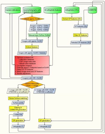
This project encompasses such an SfM+MVS software approach as it is the only method that can be used for the millions of vertical and oblique APs that are waiting in archives to be processed (see flowchart) Besides, this software method can be applied by everyone that does not have the necessary hardware for the second integrated solution.
In a nutshell, the software should first check if any information is available on the images exterior position (ExPos) and rotation (ExRot). If this is not the case, a necessary manual step is included to input some rough location information.
Subsequently, features are extracted from the aerial image(s). After checking available inner orientation data (IOR), a corresponding set of 3D orthophoto features is acquired from a dedicated database. The latter is generated by combining DTM information with features resulting from orthophotomaps, thus providing a substantial and valid 3D set for matching with the ungeoreferenced aerial footage. Great care will be taken to keep this database with 3D orthophoto features accurate (e.g. only 3D points from terrain and not from vegetation) and up-to-date.
The theoretical software workflow.
During this matching step, the inner and outer orientation of the image(s) are calculated. In the case of a set of overlapping images, this process has to be extended to a bundle block adjustment of all features, allowing for further refinement.
Finally, an accurate georeferenced orthophoto of all APs is calculated based on the orientation information of the APs and the given digital terrain model. In case the available DTM/DSM is not sufficient (e.g. too big grid width, missing surface details, temporal changes), dense surface matching techniques will compute a new DTM/DSM to be used in the orthophoto production. Based on the adjustment procedure, the final accuracy of the orthophoto can be stated.
This accuracy will depend on various local influencing factors:
- the APs used;
- the orthophotomap and DTM used for the orientation;
- the accuracy of the orientation parameters;
- the DTM/DSM used for the orthorectification.
Generally, the absolute accuracy of the geolocation of the resulting 2D orthophoto of the Aps should correspond to maximally two to four raster cells of the given orthophotomap (typically an orthophoto with 0.25 m raster width will be used).
Automated (ortho)rectification of archaeological aerial photographs
Franz-Klein-Gasse 1
A-1190 Wien
T: +43-1-4277-40486


